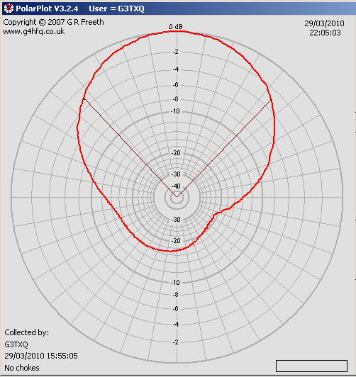

This is what S-meters look like:Īt HF I've had good luck with a test setup like this:Ī CW/SSB receiver with the AGC off is a pretty linear transducer from an RF carrier into an audio tone, and good true RMS multimeter or sound card scope will measure relative voltage pretty accurately.įor antenna patterns, I use G4HFQ's PolarPlot (again with the AGC off on a CW/SSB RX) Just testing with repeaters and S-meters seems really sloppy. What equipment, physical space, and procedures do I need to figure out if the lobes are where they're supposed to be, and measure the gain? Any traps for younger players I need to watch out for?
G4HFQ POLARPLOT HOW TO
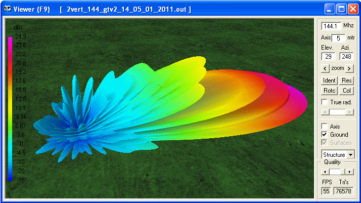
My question for the forum is, what do I need to buy (or build) to test the signal pattern? I'd like to see if its performance matches MMANA's predictions, but I don't know how to go about it.

This is the first time I've modeled and built an antenna without following someone else's calculator or design. I pulled out some wire, slapped it together, and was amazed that the prediction was accurate within a couple percent as far as the impedance figures were concerned. As a bonus, MMANA estimated 13 dBi gain and >20 dB front/back ratio. So I went dinking around in MMANA, tweaking spacing and lengths, etc., until I ended up with a 4-element yagi with 50 ohm impedance and negligible reactance. I was reading up on yagi design, and ran across a comment (maybe it was Cebik?) that said that element separation and length are parameters that affect feed point impedance.


 0 kommentar(er)
